Tuesday, April 30, 2013

Cowl Mods Update


 We briefly interrupt the cooling articles for a quick cowl update!

The cowl had to be modified to allow it to clear the exhaust. The shapes are laid out using welding rods as splines, covering the shape with sheetrock seam tape next, then filled with lightweight joint compound. After sanding to shape. The entire area is covered with plastic tape as a mold release and the fiberglass is applied. Before removing the glass, reference holes are drilled, then the glass removed. Next its trimmed to shape and glued back in place with Gorilla Glue using clecos as clamps. Sand and fill...


Since discovering spline method of making complex shapes, I am not going back to glass over foam or clay anytime soon! I am still messing around with the process and will write it up after I figure it out completely. Its kind of a mix of cutting foam cores for model airplane wings and finishing your basement ; )

Below are the first test shapes. 


Splines from below covered in joint tape


Sunday, April 28, 2013

VW Cooling Part 2

Here are a few additional areas to address when it comes to cooling.

Pipes exiting the cowl in high pressure areas
On a Sonerai with short exhaust stacks, the front two pipes are in a high pressure area of the cowl. The openings around the pipes have to be big enough to allow for the cowl to be removed and attached easily. This leaves gaps that allow a significant amount of air to pass into the lower side of the cowl that disrupts cooling efficiency.

To address this issue on the first set of exhaust pipes for the Sonerai, I used a fiberglass material that is used to form the seal for a wood stove door. They were held in place with the cement that is used to hold them in place on a wood stove and then wrapped with safety wire.

Seals added to the pipes 
 These seals are placed at the exit hole for the exhaust pipe, touching the cowl to seal the area.
Seals as seen from the bottom

 To both reduce drag and eliminate the need for these seals the exhaust pipes were reworked to exit the cowl in a lower pressure area at the bottom of the cheek.
"Ram's Horn" exhaust pipes used to move the exit locations of the exhaust pipes


To further minimize the leakage around the exhaust pipe exits, aluminum plates were fabricated to prevent burning of the cowl and the exhaust pipes were cut to be flush with the exits. This also made the cowl much easier to install and remove. 

Flush cut exhaust pipes


I have seen much discussion about whether or not exhaust pipes should be cut flush with the cowl or not. Some say that it will damage or burn the cowl. I have not had any issues with using flush pipes since I have been using them in one form or another since 2007. 

The turbo exhaust system will be cut flush and trimmed with a stainless steel plate due to the higher temperatures associated with the turbocharger


More to come as time permits!

Sunday, April 21, 2013

Cooling and the VW

The subject of cooling came up recently (and thanks for the input Dave!). Here are a few picts of the things done to keep the little VW that powers Skye Racer cool.

Back when the plane was still flying in primer I installed a ground adjustable cowl flap to determine the optimal cooling outlet size. After I found the opening size at which speed went down and cooling stayed the same I made a fixed outlet of the same area.


The VW comes with what are typically referred to as "cool tins". In airplane speak they are referred to as inter cylinder baffles or shell baffles. Cool tins pretty much suck (in a bad way) letting massive amounts of air to get by the cooling fins without picking up any heat. I had found an article about a KR builder that had used fiberglass to make form fitted versions.

Here is a picture of my original set of "cool glasses" from the top. The bottom looks much the same. They were ultimately discarded since the engine would not cool properly. However, I have learned a lot since then and my most recent set look much the same but with "lips" on the inlet and outlet to reduce turbulence.


Oddly enough he concluded that they did not work... I have consistently seen head temps in the 350 degree F range @ WOT when measured under the spark plug for the past 6 years.

In 2006 I removed the 1850cc engine and built a 2110cc engine VW for the plane. Here is a quick pictorial guide to how I made the new "Cool Glasses" which have been in place since 2007.


Fast forward... One of this winter's mods was to add a 2"longer prop extension and a 2" smaller diameter spinner. The purpose of these changes is twofold. First, allow enough room to install a properly designed diffuser. Secondly, reduce frontal drag.

One of the pains that we VW airplane guys face is the annoyance of the exhaust pipes exiting the front and back of the heads rather than the bottom. Usually this forces our front two pipes to pass through the cooling plenum. The longer extension and smaller spinner allow for a lower drag cowl shape and a properly proportioned diffuser into the top cooling plenum without the exhaust pipes interfering. Below is a preliminary visualization of the new nosebowl shape.


Stay cool! (pun intended)

Friday, April 19, 2013

Turbo Project Update

The 4 gear pump solved the turbo drain issue. I got a few more test runs on it and a little bit of taxi testing just to see how it pulled from a standstill. Wow is about all I can say! So far I have run it up to about 55" or about 13psi but that is as far as I am going to test it. I figured that if I was going to blow it up I should do it before the motor gets torn down.

The air is still cold here, in fact I am watching it snow out of my window as I type this. With the power set at 45" the its drawing more than 9gph. The gauge was still climbing when I pulled the power back but its safe to say that it is making more than 100hp at 3500rpms. The log file from the ignition shows that 55" spun the prop up to just under 3785rpms static, a full 900rpms more than it would without the turbo.

Boost comes on at 2900rpms, which was the max static rpm before the turbo. Throttle response and engine acceleration is actually better than it was before the turbo and carb change. I attribute it to that shorter intake manifold and the bigger carb. The turbo is free ranging, meaning that there is no wastegate so your throttle hand is what controls boost levels. Once its boosting, it takes very little throttle movement to make a lot more power. I ordered a wastegate and the solenoid required to let the ignition module control the boost but I am not going to install it until after I can see how hard it is to manage in the air. At this point I have collected all of the data that I need so its time to move on to the cowl and cooling baffles.

 The first step was to mock up what I thought the cowl could look like using photoshop. It will look something like this:  


Next was to clearance anything that was hitting the cowl and cut off the existing nose bowl.


Tomorrow the foam shaping begins!

Sunday, April 7, 2013

Turbo Drain Update

After multiple test runs with various fixes, it became obvious that the a gravity drain was just not going to work. I already had a 4 gear CB Performance dry sump oil pump but was not ready to invest the time to dry sump the entire oil system. What I did was convert the pump to use the larger set of gears to feed oil to the engine and the smaller set to pull oil from the turbo. This video gives an overview of the pump and covers what is required to convert the pump.

This conversion solved my oil drain issues, but I could also be used to pull excess oil from the valve covers and possibly pull a partial vacuum on the case.


Friday, April 5, 2013

Alternative Carbs - The Mikuni SBN

Mid last year I started toying with different carbs on the Sonerai. I dug through a bunch of dyno sheets of 2110cc engines with the same cam and heads in cars and found that they made about 25hp more than I was at 4000rpms. The only difference was the carb size. I spoke with a few people (like John from Aircooled.net) about the proper cam and compression ratio for my engine and they could not figure out why in the world I would run a single 34mm carb.

 I spent quite a while looking for a carb that was inexpensive and tunable both on the ground and in the air and found the SBN being discussed on a shifter cart website. Turns out that these guys also adjust their mixture during a race. It was used on performance watercraft before fuel injection became common.

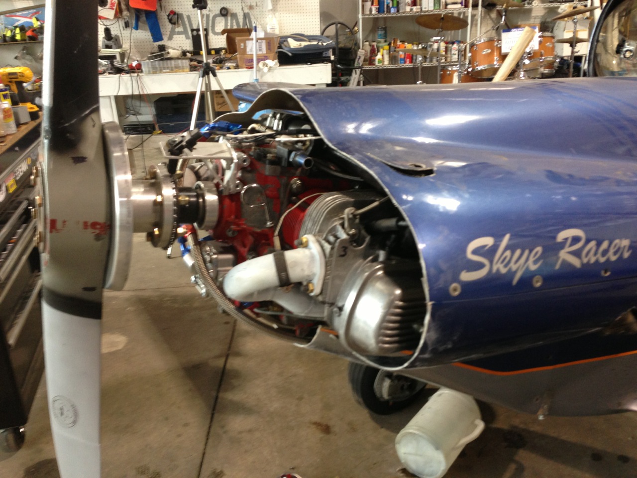
After determining that the carb is going to work out by using my father in law's identical carb from his jet ski, I bought the one for the Sonerai today. 
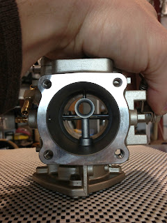
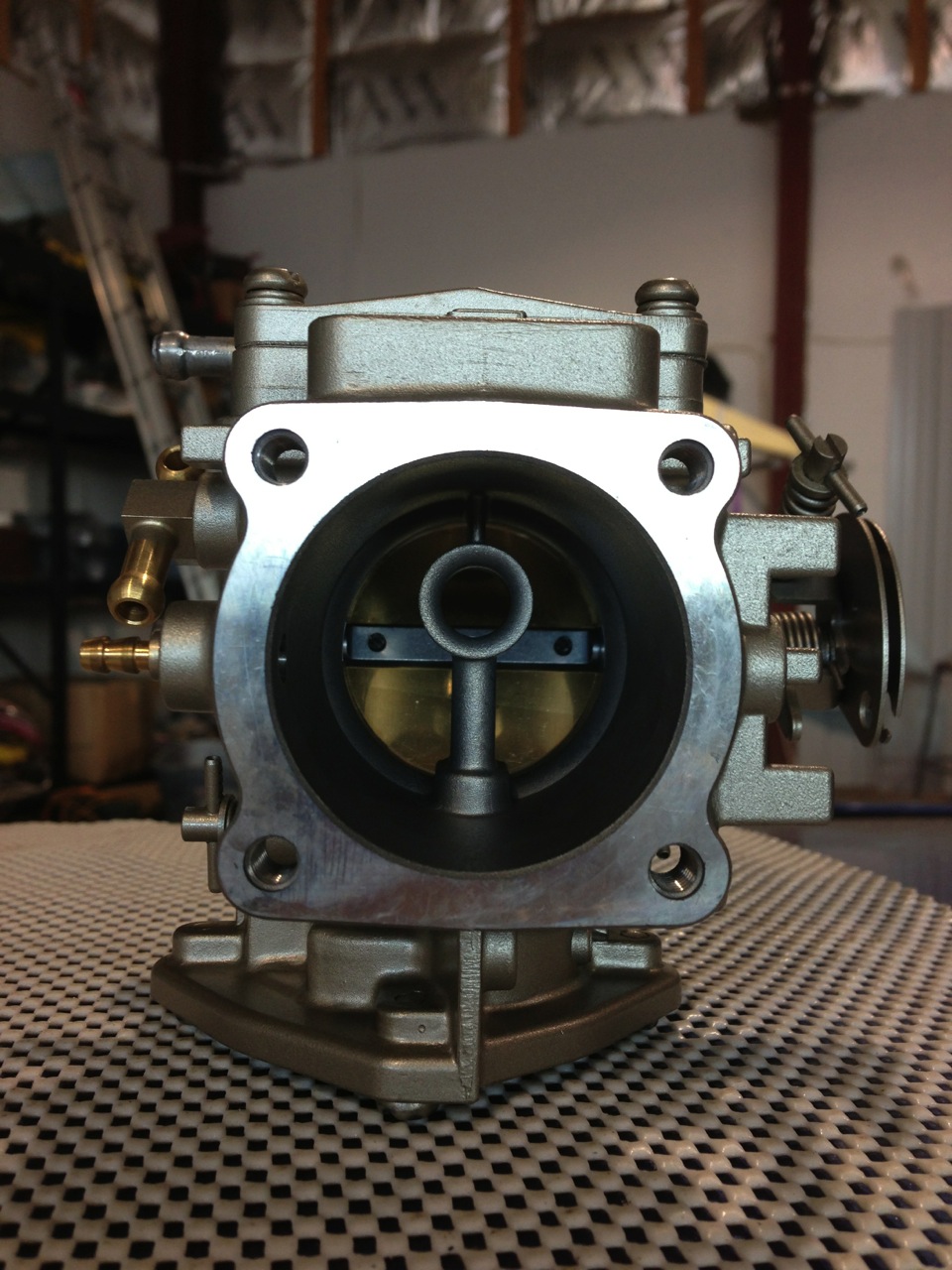
Its a Mikuni Super BN Series 44mm Carburetor part number BN44-40-8067. It has a 44mm throat and a 40mm venturi.

Modifications for aircraft use are minimal:
- Remove the throttle return spring
- Install a normal throttle control arm
- Fabricate a throttle cable bracket
- Modify the high speed adjustable needle to accept a control arm and fabricate cable bracket

I am doing a couple of other things for my installation that would not have to be done
- Block off the onboard fuel pump. If I was not running a turbo I would have likely kept it as a backup and plumbed the pulse line to the intake manifold.
- Tap the fuel inlet and returns for 1/8" NPT so that AN fittings can be used.
- Added a bracket to hold the throttle position sensor

The carb with just about every possible needle and tuning jet cost me $204. A much nicer number than the other options available for our little engines! Tuning and tweaking will start this weekend. If anyone is interested, here is a link to the manual for the SBN series carbs: http://www.mikuni.com/pdf/sbn_manual.pdf