(skip to the end if you don’t care and just want to see the
baffle progress ; )
Its been 18 months since the Skye Racer last flew and one
might ask “why do you keep tearing a perfectly good airplane apart?” Speed
right? Not actually. It’s about learning…
I love to learn new things. I enjoy digging into how things
work and solving problems. My long term goal is to use what I learn and design
cool airplanes. I have been working on a two seat design on and off with the
help of my friend Ed Fisher for a few years.
That may shed some light on why I not only tear it apart
constantly, but is also why I do things three or four times even though the
earlier attempts could have been considered acceptable. I have no interest in
building show winning airplanes. They can’t look like crap, but I must confess,
I don’t always perfectly space rivets where it does not matter ; )
A Sonerai is a perfect platform for this type of
experimentation and learning. It’s a forgiving airplane with a relatively slow
stall speed and fairly large tires, just in case one of the experiments goes
wrong. With the VW engine, it’s inexpensive to make changes to. Even with
ported and polished racing heads, a complete top overhaul is about $800. A cam
is about $100 with hundreds to choose from. If you want to raise or lower the
compression, its $10 for a new set of cylinder shims.
Turbo Sonerai Project
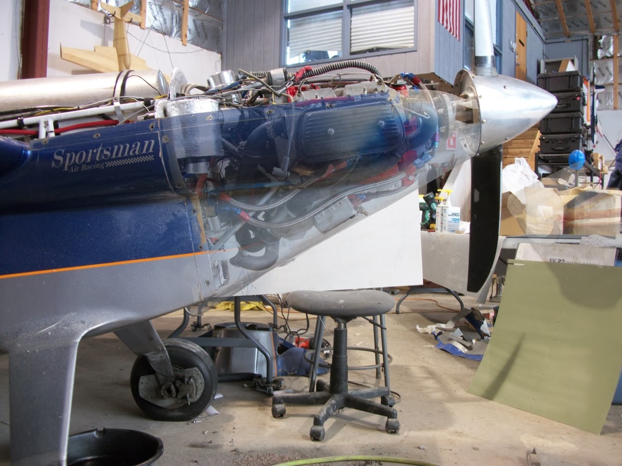
When this latest project began it did not include
turbocharging. I was designing a tuned intake manifold, 4-1 exhaust and looking
for a new carb. I also wanted to reduce cooling drag which is why I extended
the nose of the airplane. Turbocharging only came into the picture after I
realized that a tuned intake manifold and exhaust required a lot of space. While
I have often referred to it as the “Turbo Sonerai” project, that’s not how it
began.
With cooling drag reduction being one of the primary goals,
I was not willing to rush the cooling baffles to make the 2013 Airventure Cup
race. I had worked too hard on the cowl to make more space available to slop
something together.
Back To the Baffles
The goals for the new baffles were simple. They had to have
no leaks and be easy to remove and install. The shape had to be as efficient as
I could make it within the available space. My last set of baffles sealed and
cooled the engine well, but they were horribly draggy. The required stupid
amounts of silicone to hold them on and seal them. They took about 2 hours to
remove and install, mostly because of the amount of old silicone that had to be
removed. After they were reinstalled I had to wait for the silicon to set up,
which would take hours.
I had originally intended on making another set of composite
baffles using poured urethane foam as a plug. With a week or two left before
the race, I thought I could get them done in time, but I was out of epoxy and
did not want to make a huge mess with the foam and glass process. I thought I
could get them done easily out of aluminum. I leaned that while I was a
competent with typical A&P type sheet metal tasks, my experience and
available tools were not up to the task of quickly making the kind of baffles I
wanted.
After an estimated 80 hours, I am finally almost done with
the first side. The upside is that I learned a lot and now have a baffle that
seals with nearly no silicon can be removed and reinstalled in 10 minutes.
That brings me up to today. There was one part of the baffle
that I resorted to using composites. It was a compound shape caused by the need
to stay out of the way of the intake tube coming off of the turbo. I tried to
meet my design goals with aluminum three times and was not willing to start
banging on metal with a hammer and sand bag. I gave up and went the plastic
route.
To make the part, I used wire mesh to conform to the inside
of the baffle and covered it with aluminum tape. I smeared it with silicone to
fill in any weird spots and act as a mold release. I then covered the area with
2 layers of heavy carbon fiber. Its still needs to be trimmed and attached but
at least the shape is done!
Next up is to create a lip for the cooling inlet and come up
with some type of perfect seal between it and the baffle while still
maintaining the effectiveness of the divergent duct.
I started on the other side while waiting for the hanger to
warm up enough to do a layup. The other side is going to be much faster!