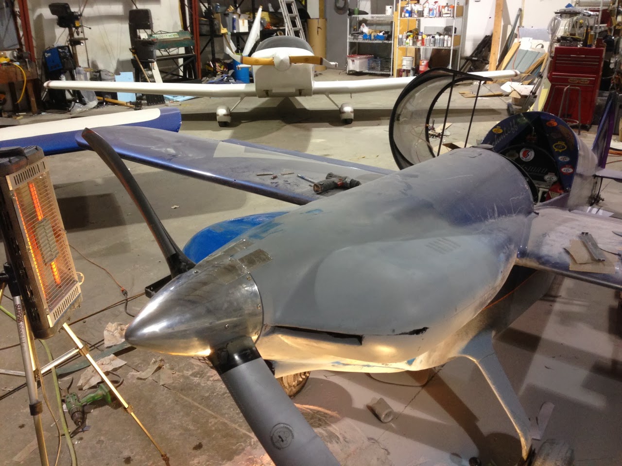
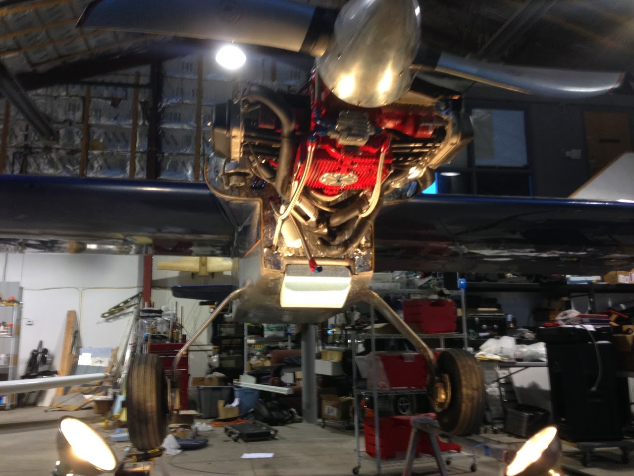
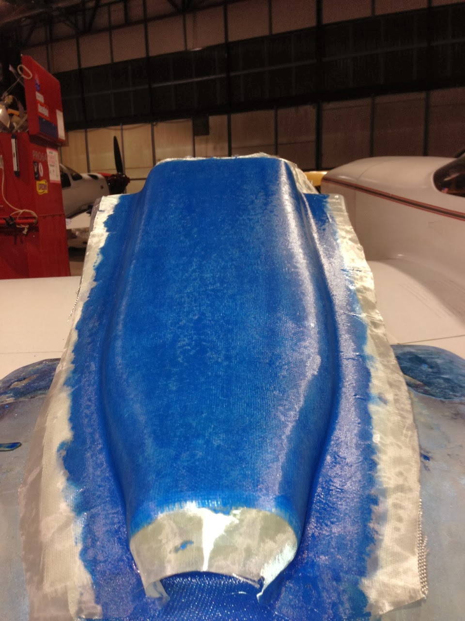
Lots of late nights at the hanger for the last 10 days. I have been finishing up the shape of the cowl as the main focus, with other projects in process as I wait for layups to set up.
Here is where the cowl is as of tonight. The basic shapes are done and I am ready to move on. The lower cowl still needs some filler below the inlet to smooth the transition but that will now become a side project.
Between layups, I started on the seat modification that will allow me enough room above my head for a helmet. To lower the seat height, I have to build a control assembly that is smaller than the original. The stock torque tube is 1.5" and used tall phenolic pillow blocks. By reducing the torque tube to 1" and revising the seat pan I can gain about 2.5" of height above my head.
Rather than using split pillow block, I decided to make two slip on blocks out of aluminum using a drill press and a mill vice. Not a great way to make them, but I have to work with what tools I have available.
I added a grease fitting and a grove internally to lubricate them.
Below is the seat area. I followed the plans originally by adding steel straps between the outer tubes of the seat frame. Not exactly sure how to make the new pan yet, but I have a few ideas.
One thing is for sure, I am ready to be done fiberglass work for a while...
Random offerings of nothingness negated by actual reality.
Friday, February 28, 2014
Sunday, February 23, 2014
Finishing the Cowl Shape
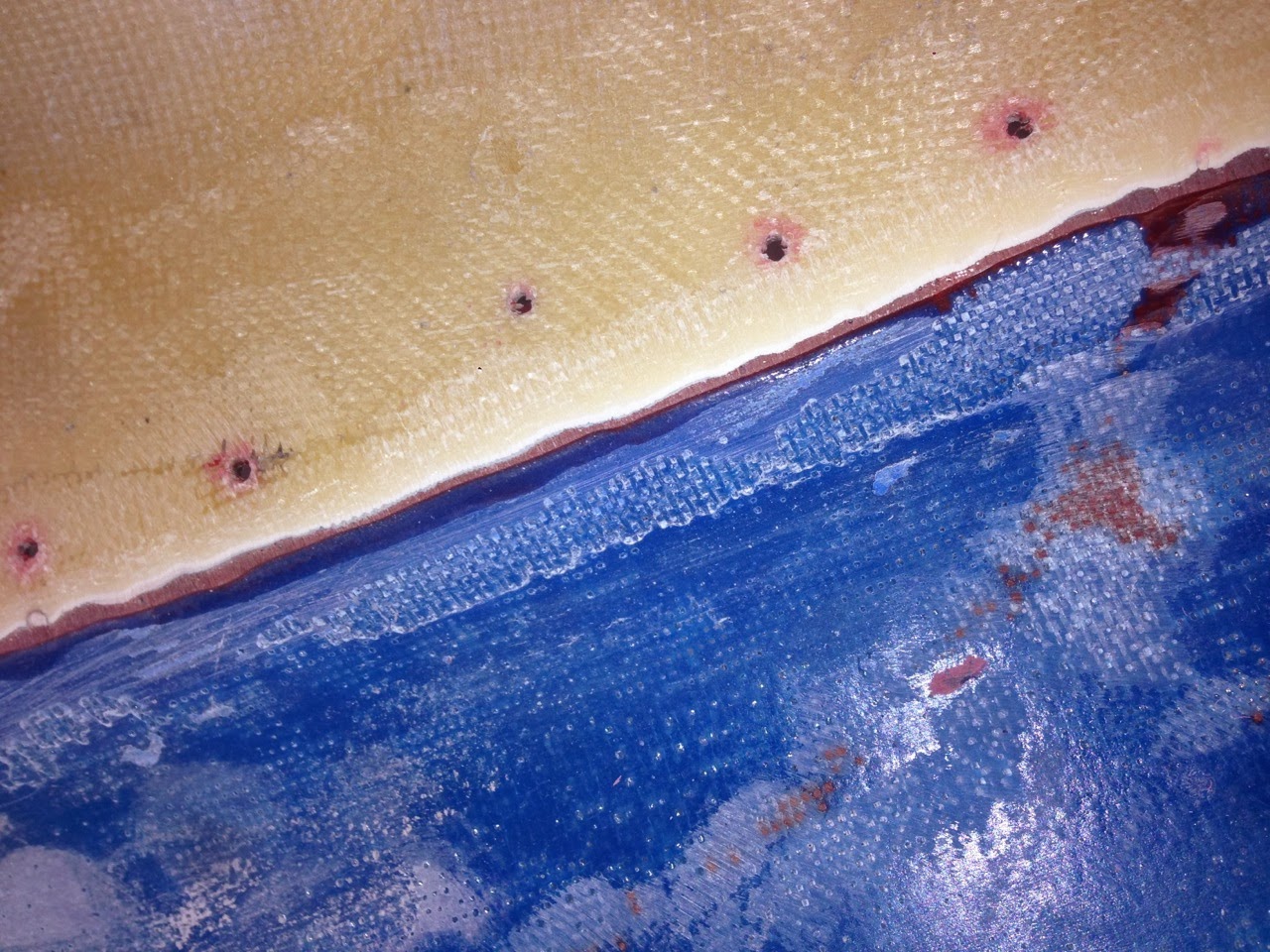
Here is why I keep saying "the epoxy is dyed X to aid in sanding". As I have mentioned in the past, there is very little left of the original cowl. The pictures below are of the inside of the lower cowl, where the new oil cooler duct is glued into place. The dye makes it easy to see when I have sanded away the remainder of the original cowl to meet the new piece. It also makes it easy to identify where the runs are, and when sanding them out, see when you have removed them.
Below you can see the difference after a bit of blending. The cowl cheek on the left of the picture has been rough blended, the right has not been touched.
Here is another example of where dying the epoxy helps. Below I am just starting to sand the top cowl to its final shape. Since the new nose bowl shape was laid up over a plug, the epoxy had to overlap the existing cowl. To get back to the shape of the plug, I had to lay up glass on the inside of the cowl to bond the two together. I ended up laying up quite a few layer of mat glass (dyed red) to give myself lots of depth to blend the two pieces together. Having the epoxy dyed a different color lets me see how deep I am sanding.
Below you can see the difference after a bit of blending. The cowl cheek on the left of the picture has been rough blended, the right has not been touched.
Today I continued to work on blending the cheeks and fixing a number of other alignment issues. The two pictures below show some further blending of the left cheek, both lower and upper. I am still not happy with the shape on the bottom. I will have to add a bit more mat glass to it and continue to blend them together.
I had hoped to get further with it this weekend, but this stuff takes time. More to follow as I continue to blend the cowl to its final shape.
Friday, February 21, 2014
Finishing the Cooling Outlet
About the new filler I used... When I mentioned that it does not sand as nicely as the lightweight spackeling, well that was the understatement of the year. Its like sanding a rock. It ruined 80 grit sandpaper in short order. I had to resort to using the straight line pneumatic sander with 36 grit to shape it.
Learning from previous blunders, I taped the first layer of glass into position and wetted it. Instead of waiting until it was cured and repeating the process, I waited until the first layer was well on its way but still sticky and wrapped the second layer around the first.
Here it is with 2 layers
After curing, trimming and bonding, its looks like this:
Tomorrow is a big day as I am going to do the final external shaping of the rest of the cowl. I will finally get to see what its going to look like (for a while ; )
Thursday, February 20, 2014
Details, Alignment and Details
If I have learned one thing through this project as that if you are going to change anything about the cowl, alignment is the key. When I made the nose bowl, I did not realize that the oil cooler and a random screw was touching the cowl. It may not sound like a big deal, but as soon as you fix the interference problem, everything is out of alignment. Fixable, but it all takes time.
I have not gotten much visual progress done as of late. I sorted out the routing and fittings for the oil lines. It seems that I never quite have everything I need when it comes to plumbing. Over the years, I have gathered enough brass and AN fittings to set up my own store, but I still need one more.
Temporarily accepting defeat on the pluming, I moved on to bonding the new lower cowl piece to the existing cowl. I knew when I decided to create the lower cowl shape without it being connected to the plane that it would change once I got the upper and lower cowl in place, but as my friends from the moving industry say "we'll fix that in post" which in airplane terms means with micro later.
So with about 11th billion clecos, I glued it in place. I used West systems epoxy with red dye, again to aid in sanding.
Using the hoist alone to keep the plane in the air requires that the top cowl be off of the plane, but since I need everything screwed into place to keep things aligned, I grabbed a section of catwalk that I had laying around and lowered the plane on to it to make the work on the cooling outlet easier.
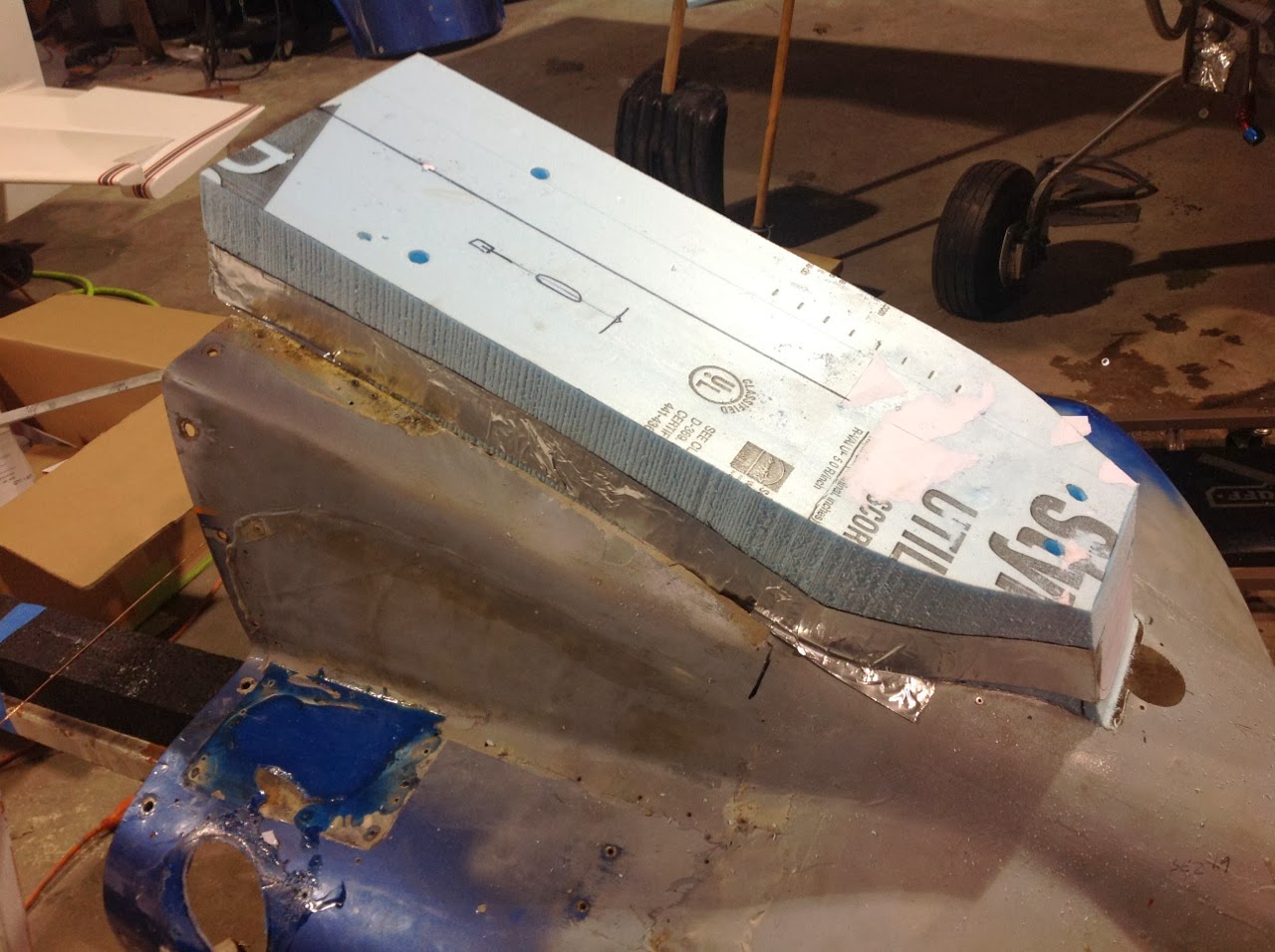
I started off with blue foam and roughly shaped it last week. To finish the outlet, I used Scotch 77 to glue it to the existing outlet ramp. Instead of using the lightweight spackling compound that I usually use over foam, I tried another compound. Drywall guys refer to it as "hot mud" since it does not dry, but cures, and does so in about 15 minutes. It does not sand as nicely as the lightweight compound, but its faster and much stiffer. No matter what you use for filler, working on the bottom of something with filler is a pain.
Not a great photo, but the rough outlet shape can be seen. This outlet piece starts at the firewall and the final area where the air comes out is necked down forming a convergent duct.
Hoping to get some glass on it tomorrow morning before work!
Tuesday, February 18, 2014
Time to put it in the air...
Not flying, but just up in the air to make the completion of the oil cooler installation, bonding of the new bottom cowl piece, installation of the new wheel pants and cooling outlet construction easier.
I have 3 sets of electric hoists in the hanger. Two sets are on the one side, one has my Smith Miniplane fuselage on it, one is currently open. The center hoists are rated to lift 2200 lbs and they are usually used to store the Sonerai over the winter (on the rare occasion that I don't completely tear it apart). The more common use for the center hoists is to get the plane up off the ground to clean the belly.
Getting the plane up in the air with them takes a matter of minutes as seen in this video:
I lifted it up and rested a little of the weight on a pair of saw horses to finish up all of the nut plates that hold the cooler in place. While its up, I intend to finish making the oil lines as well.
I also removed the oil cooler duct from the cooler and got it trimmed. As you may notice, I still have some filler to scrap out of it before its bonded to the cooler.
Pretty boring stuff, but its a few more things off of the list...
Monday, February 17, 2014
Finishing the Oil Cooler Duct
Not much time to work tonight, but I got a few things done.
Now that the duct is fully set up, it was trimmed to size and the foam was melted out. It was quite a messy process. My hands will be covered with dried blue ectoplasm for a few days ; )
Next it was trimmed and aligned using the cooler and the front template, then held in place with aluminum tape.
The cooler was wrapped in plastic tape as a release agent and the bottom and sides of the duct were glassed to the cooler. It is wrapped around the cooler at this point so that its alignment is held while I remove both the duct and cooler to glass the top of the duct to the cooler.
Here it is with the brace removed.
A quick check to make sure everything is still aligned:
Then the cooler and duct were removed to glass the top flange.
After drilling the attachment holes in the duct to the cooler, the next step is to bond the new lower cowl piece into place and finish off the outlet duct. I will loop back and finish the inlet at the same time as I finish off both cooling inlets. The list of things to do is finally getting shorter...
Sunday, February 16, 2014
Inlet Duct Progress
The first step was to hotwire a straight piece of foam that allows for the interface of the removable scoop (easier to show once I get there rather than try and explain).
Next step was to make a jig that would hold the inlet template in place once the external scoop was removed.
Once the scoop was removed, I stacked foam and glued between the face of the cooler and the template.
From there the foam was shaped and blended between the two shapes. Plywood templates were used on both ends as a sanding guide and to prevent screwing up either end.
After sanding and filling, the part was checked for alignment.
Of course I usually have to make 2 or 3 parts before I figure out what I am doing ; ) The blue one below was the first attempt. I abandoned it because the top of the duct was flat and I wanted to get the air to change direction before heading through the cooler.
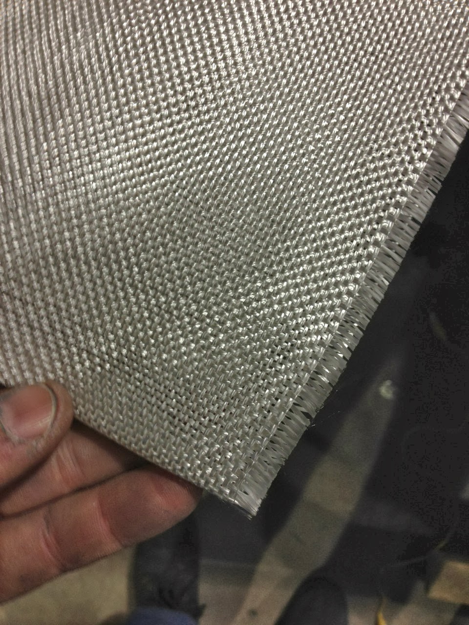
Next was the layup, which was a layer of deck cloth first to keep the inside of the duct as smooth as possible and then 3 layers of heavy glass. Both had to be cut on a bias to make the curves. Looks more like a murder scene than fiberglass work ; ) I usually use epoxy dye with resin and filler, alternating colors as a sanding guide, but this is red just to match the engine ; )
While waiting for the resin to set up, I started working on the convergent duct part of the cooling outlet.
Here is the trimmed piece. Next it goes back in place to layup the flange to attach it to the cooler, then the removable part of the inlet.
Friday, February 14, 2014
On to the Inlet Duct
I had limited time to work on the plane today, but I snuck out to the hanger before work to pull the part off of the plug, trim it and make sure it cleared the oil cooler. Below are the results.
Thursday, February 13, 2014
More Lower Cowl Progress
I did not have much time to work on much tonight, but I got the cowl to the next step.
I ended up changing the oil cooler inlet angle and extending it to get it out of the boundary layer. After the rough shape was sanded and filled, I sprayed the entire bottom of the cowl with PVA and waxed it 3 times as a mold release.
The layup was done in two steps but together. The first three pieces of glass went just in front of the inlet using a fairly light cloth. The next step was to lay up two layers of pretty heavy glass and then a layer of deck cloth over them to make finishing easier.
Next up is to add a radius to the front of where it is trimmed in the picture and hollow out the foam to form the first 2 inches of the inside of the inlet.
This thing might be back in the air this year after all. Yippie!
I ended up changing the oil cooler inlet angle and extending it to get it out of the boundary layer. After the rough shape was sanded and filled, I sprayed the entire bottom of the cowl with PVA and waxed it 3 times as a mold release.
The layup was done in two steps but together. The first three pieces of glass went just in front of the inlet using a fairly light cloth. The next step was to lay up two layers of pretty heavy glass and then a layer of deck cloth over them to make finishing easier.
After they started to set up, I trimmed the inlet and outlet area (which is not the final shape) to see how it looked, and that is where I left it for the night.
This thing might be back in the air this year after all. Yippie!
Lower Cowl Plug
After trying a few other methods of making the plug for the lower cowl, I finally braced it and cut a giant hole in it. That allowed me to use flat pieces of foam to create a shape.
I drew the inlet shapes in CAD and rough cut the foam on the bandsaw, then screwed it to the braces.
From there I used a welding rod to lay out the curves and used aluminum tape as the guide for the hot wire.
From there I rough sanded it to shape by eye, then coated it in lightweight spackling compound (with blue epoxy dye) so that I could see what the shape really looked like.
After numerous applications of filler, it looks something like the picture above. I still have to finish shaping the inlet and finish sanding, then its on to spraying some PVA and laying up the glass.
Between sanding the blue foam and the blue filler, I pretty much look like Grumpy Smurff ; )
Saturday, February 1, 2014
Convergence, Divergence and Other Project Rambelings
I think I am getting the picture as to why most airplane builders don't attempt to optimize cooling drag. Its a pain...
So the idea is to take the air in, slow it down and thereby increase its pressure, make it flow through whatever you want to cool and then try and return its local free stream velocity. Sounds simple enough until we realize that all of those ducts take a lot of space, especially when you are trying to do it to a 40+ year old design that is very space limited to start with. There is just no room left under my cowl. The only option at this point is to make more space.
As I mentioned, I removed the Mocal 13 row cooler and picked up a Positech 5 row for an O-300. It has about the same area of cooling fins but is narrower allowing less hacking of the lower cowl. After consulting with Dick Keyt and Joe Coraggio (whose blog can be found here: Garaggio.wordpress.com ), I was going to attempt using a smile inlet under the spinner to supply air to the cooler. The problem I ran into was that a smile inlet big enough to take in the air I need looks pretty strange below a 9 7/8" spinner. Even if I could have taken the air in at that location, it would have to make a very sharp turn right after it entered the inlet.
I am pretty sure I will end up with a small rectangular duct that measures about 1.75" by about 4". This should allow me to construct a duct of proper proportions to slow the air down. The exit side convergent duct is going to be easier as I have a little more space to work with.
I think I can get the cooler up a little further into the existing collage of cowling pieces but the more I move the cooler up the more difficult the oil lines become.
Anyway, I spent the better part of the day trying to figure out how to balance all of this. The picture shows the current location and the spline depicts the rough shape of the new lower cowl. At this point, I really wish I would have just started from scratch on the entire cowl...
Whats up next:
- Permanently mount the cooler and get it plumbed
- Revise the lower cowl shape
- Make the inlet, the divergent duct and the exit duct for the cooler
- Suppress excessive use of profanity
- Build the right side cooling baffle and cowl inlet
- Lots of heat shielding
- Cowl exit duct
- Cut new pushrods and set valve train geometry
- Tidy up the baffles
- Body work and primer on cowls
Hoping to have all of this buttoned up and have it airworthy by the end of the month (which means it will take 2 months ; )
Subscribe to:
Posts (Atom)
