Friday, September 27, 2013

Project Update

Not much has changed since before EAA this year. Got the spinner polished and fit, but progress is slow. Just got it on the scales and worked out the W&B... While the CG works out and the weight is tolerable, I have officially decided to just go back and do all of the airframe mods I wanted to do.

Here is another quick video from the ground testing phase before teardown.


Here is the log file from the ignition. MAP is in kPa showing a max pressure of 189, which translates to 12.71psi of boost or 55.81". 

A couple of interesting take aways... 
- This boost pressure was achieved with 80" throttle. 
-  The timing is set to retard the spark timing from its max advance of 30 degrees at a rate of 1.5 degrees per psi of boost. 
- The timing has a max advance of 40 degrees, which can only be achieved at high rpm and no load. The ignition is tracking and performing well.


My disappointment with not flying it this year is being overcome by excitement of the rest of the airframe mods ; )

Sunday, July 21, 2013

Ready to Test Run

I have not posted for a while since all efforts have been on getting the airplane ready for the Airventure Cup. Not sure if I will make it yet, but there is a chance.

Its ready for a test run after rebuild and final install of engine and systems. Still have to build the cooling baffles and other odds and ends.


Sunday, June 23, 2013

Using Ghost Images to Aid in Aircraft Systems Design

I am kind of skipping ahead, but time is running out for me to get this thing back in the air and tested before the Airventure Cup race. I will loop back around later and detail the missing steps for the cowl construction.

I am about to finish up a few FWF details and needed to see what I had for space. I need to put the oil cooler and baffling someplace in there and also design the cooling baffles. Using the ghost images is almost like having x-ray vision!

Sam Hoskins showed me this trick (thanks Sam!). Using a tripod, take pictures of the plane with the cowl on and off in various positions. The camera cannot move between the cowl on and off pictures and its best to use a camera that has a timer on it so you are not bumping anything when the shutter fires. From there they were put into iMovie and cross dissolve transitions added between picts. Pretty easy. You will be able to find a more detailed description of the process in the next "To Fy" magazine available to Sport Aviation Association members.

Take a look at the video. Its quite useful to pause it during a transition. That is where you can really get a look at how things fit together.


Thursday, May 30, 2013

Vinylester Resin Vs. Epoxy

Nothing much different that the last time around... spray the plug with PVA, wax it 3 times and start laying the glass. The big difference was the resin I used.

In the past, I have used West Systems epoxy but when I ran out and could not find it locally I bought 3 quarts of vinylester resin. I could have used polyester, but I am getting ready to build wingtips that double as tip tanks and the vinylester will withstand fuel so I decided to give it a try.

I found it much easier to work with since it is stickier than the epoxy. When laying the glass in multiple layers at a time it held to the concave shapes much better. When using epoxy, it is a constant fight when trying to brush or squeegee resin into other parts of the layup. The vinylester kept it put even when spreading resin away from the curves (like the one aft of the spinner where the round shape joins the cheek). Its working time was just as long but it sets up much faster
which can be varied by how much MEKP you put into the resin.

The only down side is that it eats pink (or blue) foam (polystyrene). Anything that is made from it must be coated with epoxy before using vinylester over it. Oh ya, its eats the plastic cups I usually use with epoxy ; )


The seams are overlapping this time around. I laid 2 layers of glass across the leading edge first and then used 2 layers for the cheeks. A little peel ply (dacron fabric) was used over the edges of the glass to reduce sanding before the next layups. 


After the resin has set, the peel ply is removed.


A little sanding of the edges of the glass and the bottom gets glassed. The center section that was retained from the last try will also get 2 layers for a uniform thickness.

Wednesday, May 29, 2013

Cowl Rework

Well, I started over again. I did not have the splines in the correct locations. I could have made it work but I was determined to figure out how to place the splines properly.

I decided to build the shape out of foam while using the splines as a guide. Having it made of foam meant that I could screw it up and still go back and try again. This was the 4th attempt at getting it right. The sad thing was that I almost had it right on the first three tries. All of the reworks, while time consuming, will pay off in time saved on future projects. For reference, to spline, tape and prep for glass, the spline method took about four hours. Shaping the foam for the plug and getting it prepped took about 20 hours.

I am going to do a step by step write up on placing splines (with lots of examples of what not to do ; ) For now, here is how I used the splines as a guide for shaping the foam.

First I used a spline from the split line of the cowl to the spinner and made a cardboard template. I then used that to cut a piece of foam to the same shape and glued it to the cowl and spinner. Next I used the splines to rough out the angles that the splines would meet the leading edge of the cowl.


From there I stacked small strips of 1/2" foam and built it up and aft.


I again used the splines to guide the shaping process. After a few reference grooves were cut, I sanded between them to get to the final shape. Many long and tedious hours...


After lots of hours of sanding and shaping, the plug looks like below. I stuck mock inlets on it to get and idea of how it would look. I'm not totally sure where they will be or their size yet. I have to get the final part to assess what my best options are for avoiding the exhaust pipes wile still allowing for a properly shaped diffuser.


Sunday, May 19, 2013

Making an Upside Down Layup

The bottom of the cowl was more cantankerous than the top as you might suspect. I have epoxy on my shorts, shirt, arms, hands, legs and a few places I did not think epoxy could migrate to. On top of the gravity issues, the epoxy went Chernobyl in a modified aluminum can half way through fighting with the first of two layers of glass. It ended up turning into a big blob on the bottom of the left cheek but I grabbed some peel ply and smushed it against the blobs and was able to salvage the first layer of glass. 

For the second layer, I cut the glass piece in half and taped it in place before painting the epoxy on. That eliminated the delay of fighting with a huge sticky piece of wet glass that would not stick to the waxed PVA. The key to keeping the epoxy from going exothermic is to not let the epoxy sit in the cup (can) for to long. Taping the glass in place  did the trick. 


To speed up the curing time of the epoxy, I use two 1000 watt radiant heaters. Without them, the West Systems epoxy takes hours to set up. With them it takes about 30 minutes. Also in the picture below, I added a single layer of glass to join the new nose bowl to the existing cowl. I had originally planned to use a few pieces of aluminum and attach them to both the new and old pieces, but the shape is curved and I concluded that the aluminum method would not work.


After the new parts were joined to the old, I used a laser level to layout and cut the spit lines and pulled them apart. 

Bottom cowl with the splined plug still in place

Top cowl with plug still in place

I've got about 18 hours invested at this point. Lots of work to go... I am going to take the better part of tomorrow off and fly the KR in the right of the above picture ; )

Saturday, May 18, 2013

Applying the Fiberglass to the Cowl

I have a moment while I wait for the top layer of glass to set up so here is a quick update. At this point I have 12 hours into it.

After the shape was close enough, I sanded away enough space for the glass to be flush with the existing cowl.

 Sam Hoskins of Q200 fame sent me a message warning me of using silicone as a mold release. I had intended to thin bathroom silicone and brush it on but went another direction. The gent in the hanger next to me owns a fiberglass shop and he stopped by to get his boat so I asked him what he would do with it.

He recommended that I put a couple of coats of automotive primer on it first


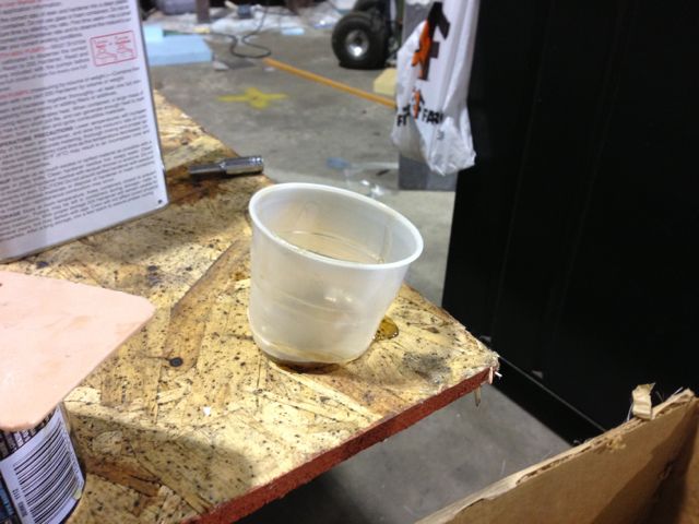
He gave me a pint of polyvinyl alcohol (PVA), and said that I should spray light coats of the material on the cowl until it took on the green hue of the PVA, then wax it three times with a mold release wax. While investigating how to thin the silicone, I came across the recommendation of using PVA and that I should be able to find it at a craft store, but I had no idea what it was nor could I find it locally. After spraying it on with a HVLP gun it forms a rubber shell that epoxy will not stick to. Pretty cool stuff.


The next step was to cut the fiberglass on a bias so that it would conform to the complex shapes. Cutting it on a bias simply means that you cut the glass so that the weave is 45 degrees.

First a coat of West Systems epoxy is applied to the cowl with a brush, then using a body putty scraper, push the glass into the coat of epoxy. Next a second layer of glass was added and applied with the scraper and a paint brush. A "stipple" brush (a paint brush with the hairs cut very short) is then used to get rid of the air bubbles and push the cloth into the corners.


From there, peep ply was laid onto the top, but the resin was starting to set up. Its not covered as well as I would have liked, but it still saves a lot of sanding later.

Next step is to take a picture while making a stupid face.


So here is where it sits. I have a radiant heater on it to speed the curing process. More picts and text as things progress. So far so good!


Friday, May 17, 2013

The Next Steps...

What happens next?

The next steps are to sand and fill until the shape is correct. After that it will be covered with silicone as a release agent, then 2 layers of fiberglass will be applied. Before the glass is removed, reference holes will be drilled. Then it comes apart, the plug removed and the nosebowl attached to the rest of the cowl, the cooling inlets cut and the pointy leading edge will be reshaped and glassed. From there the split line is cut, a joggle added and then more glass reinforcement from the inside. Clear as mud? : )


The process is actually pretty fast. Ignoring the initial attempt at the shape, I have about 3 hours into the shape as it sits in the pictures below. 


Thursday, May 16, 2013

Well, after looking at the shape for a while, I ripped it all off and laid out the splines differently. The previous shape had a flat spot on the front of the cowl. If I did not have to make the nose work with the existing cowl, I would have gone for a different shape all together, but I didn't want it to look like a complete afterthought...

I have a large picture database of fast planes, mostly Forumula I planes since they are similar to the Sonerai. I spent some time going over the different cowl shapes and decided to go with a sharper look.

The shape now converges on the 2x5" cooling inlets that start at the base of the spinner. I extended the shape onto the spinner so that the inlets will open flush with the shape. After the glass is laid up, the front edge will be modified for a more rounded shape.

The splines now converge on a center spline 
They attach to the center spline with solder
The splines now angle directly aft on the cheeks
Side view of the new shape


Saturday, May 4, 2013

Making Shapes with Splines


The first challenge was to figure out how to attach the welding rods to the existing part of the cowl. I tried the quick set JB weld first but took to long. The splines are glued on every 1" which meant I could only glue two on at a time (one on each side of the cowl. 

I scrapped that method and decided to make pads on each spline and then attach them with a slow curing cyanoacrylate (super glue). This allowed me to use the accelerator used for building model airplanes. More on this in a bit. 

The pads are made from the radiator repair putty that comes as a stick, the stuff that you mash together to get the hardening process going. I mashed the putty up, rolled it into a long worm like string and then cut it to look like rabbit droppings. 


I put down a piece of clear plastic tape as release agent and laid the welding rods in. Using a piece of wood (also covered in plastic tape) and clamped them to make them flat. The finished product is a nice flat pad with lots of surface area for gluing.


Using the cyanoacrylate, simply put some glue on the pad, position it on the cowl by hand and give it a shot of accelerator. The bond is very strong and only takes about a second per pad.


Figuring out the angles for the rods to be attached took a good bit of trial and error. The rods on the top of the cowl above and below the spinner are aimed at the tip of the spinner. The ones coming in from the side converge on the 2" area where the cooling inlets will be. Once the welding rod is positioned I glued them to the spinner backplate. 


 Each time I moved the rods I covered them with sheetrock joint tape to get an idea of what it would look like. 


After I was satisfied with the angles and shape, I cut the joint tape into 2" squares and applied them at a 45 degree angle to the spline it was centered on, wrapping the edges when possible to help keep the splines positioned properly.


After coving the rods with squares, I used lightweight sheetrock spackeling to cover the tape.


  I only did part of the cowl first to make sure I was happy with the shape before proceeding. So far so good... 


Tuesday, April 30, 2013

Cowl Mods Update


 We briefly interrupt the cooling articles for a quick cowl update!

The cowl had to be modified to allow it to clear the exhaust. The shapes are laid out using welding rods as splines, covering the shape with sheetrock seam tape next, then filled with lightweight joint compound. After sanding to shape. The entire area is covered with plastic tape as a mold release and the fiberglass is applied. Before removing the glass, reference holes are drilled, then the glass removed. Next its trimmed to shape and glued back in place with Gorilla Glue using clecos as clamps. Sand and fill...


Since discovering spline method of making complex shapes, I am not going back to glass over foam or clay anytime soon! I am still messing around with the process and will write it up after I figure it out completely. Its kind of a mix of cutting foam cores for model airplane wings and finishing your basement ; )

Below are the first test shapes. 


Splines from below covered in joint tape